Data Model
IEEE 8500-Node Test Feeder
An IEEE Working Group specified a set of distribution test circuits [CIT9] and we have chosen the largest one of these as a sample circuit for GridAPPS-D which is IEEE 8500-Node model [CIT10]. The original 8500-Node test feeder operates at 12.47 kV and has a peak load of about 11 MW, including approximately 1100 single-phase, center-tapped transformers with triplex service drops. Loads are balanced between the two center-tapped windings. The circuit includes 4 shunt capacitor banks and 6 voltage regulator banks, making it a reasonable test for solving voltage problems such as VVO. The circuit is splitted into three substation and several new distributed energy resources (DERs) are added in the test case (See Fig. 3). In addition, 7 tie switches are added such that each substation can share the load of another substation during fault to restore the outage customers. A new set of loads is added near S2 and the region is referred to as a new neighborhood.
The detailed model of this feeder can be found at:
https://github.com/GRIDAPPSD/Powergrid-Models/tree/develop/blazegraph/test/dss/WSU
The OpenDSS data can be extracted here:
https://github.com/shpoudel/D-Net
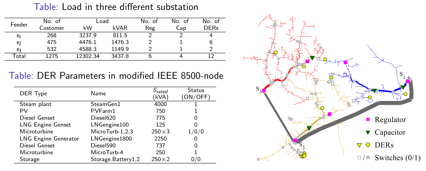
Figure 3: Modified IEEE 85000-node feeder.
The model in GridAPPS-D came from the IEEE 8500-Node input files distributed with OpenDSS, exported to CIM from OpenDSS, and then imported to the GridAPPS-D data manager. In this automated process, four changes were implemented:
Use constant-current load models, rather than constant-power load models. This is necessary for the solution to converge at peak load. Voltages at peak load are low, and a constant-power load will draw more current under those conditions. Holding the current magnitude constant allows GridLAB-D to achieve convergence under a variety of operating conditions. This is an appropriate compromise in accuracy for real-time applications, which need to be robust through wide variations in voltage and load. In contrast, planning applications usually need more accurate load models, even at the possible expense of re-running some non-converged simulations.
Disable automatic regulator and capacitor controls. The volt-var application, described below, will supersede these settings. If a developer or user is testing the GridLAB-D model outside of GridAPPS-D, these control settings should be re-enabled in order to solve the circuit at peak load. That requires manual un-commenting edits to the GridLAB-D input file.
Substitute a variable called VSOURCE for the SWING bus nominal voltage. This needs to be set at 1.05 per-unit of nominal on the 115-kV system (i.e. 69715.065) in order to solve at peak load. Other conditions may require different source voltage values.
Use a schedule for the loads so they can vary with time during GridAPPS-D simulation. The file should be named zipload_schedule.player.